It's been over a year and a half since I unveiled a new supercharged car. My move to Tulsa cost me a lot of time between preparation, the actual move, setting up shop, finding a good welder etc.
This car is a little different from any of the other I have built. It's a customer's 1984 GTV6 with my blower kit, SDS fuel injection, an intercooler, and water/methanol injection. I designed a totally new piston for this car, as nothing on the market was right for this application. The car also has cruise control and combined with the routing of the intercooler hoses prevented me from plumbing the intake side of the supercharger in my normal fashion. To solve this I stole a page from the Barry H. playbook as you will see.
I will start posting pictures and more details over the next few hours. I am loading them on my computer now.
Greg Gordon,
www.hiperformancestore.com
-
Greg Gordon
- Verde

- Posts: 1552
- Joined: Mon Nov 29, 2004 7:06 pm
-
Greg Gordon
- Verde
- Posts: 1552
- Joined: Mon Nov 29, 2004 7:06 pm
Everytime I go to a car show with a supercharged car, I get the same question over and over "what are you doing about fuel?" I am surprised I get that question so much. Fuel is by far the easiest problem to solve. There are so many options it's amazing. Just to name a few, and in no order are Megasquirt, Gotech, SDS, Emerald, Autronic, and at least a dozen others. It's also entirely possible and somewhat practical to modify L-Jet for the job up to about 10 pounds of boost.
Few people every ask, why did I use a 62 cubic inch blower and not a 90, or for that matter why not a 45 and just spin it really fast. That sure would save on space! Why is the throttle on the discharge side? Why does it have two bypass/blowoff valves? How do I know how much water or water/methanol to inject? There are a million good questions, but it seems all I ever hear is "what about fuel?".
So, I will start with fuel. This car uses the SDS system. I like it because it super reliable very easy to set up, and very good at what it does. It's not a fancy system with traction and launch control, but it has every feature I could possibly need. It controls fuel and spark very well. It can pulse big injectors fast enough to get good idle qualities. It has a ton of performance and safety features. It's the only aftermarket automotive system I know of that's used on airplanes, and that says a lot about reliability. If you want to read more about it go to www.sdsefi.com
In this application it's set up with my Stage 4 injectors. Pretty much everything else in the fuel system is stock including the fuel pump, fuel rail, and pressure regulator.
The system does not use a toothed wheel to sense crank position. It uses magnets that are embedded into the supercharger crank pulley.
Here is a picture of this car's pulley and crank position sensor installed on my shop's test engine. Note that this car has the later A/C compressor so that's what I have on my test engine.
- Attachments
-
- SDSsensorandpulley.jpg (52.56 KiB) Viewed 10056 times
-
Greg Gordon
- Verde
- Posts: 1552
- Joined: Mon Nov 29, 2004 7:06 pm
In next photo my dad is holding the SDS controllers. The little knob allows you to make quick mixture changes on the fly. This is quite useful. The bigger box is the main controller. I allows you to change just about everything. It also knows everything about what's going on in the system. You can read O2 voltage, injector duration, coolant temp sensor, air temp sensor, or just about anything else associated with the injection system on this box. It also has built in O2 logging.
I can't stress how easy it is to tune this system. Installing it is a lot of work, as are most complete injection and ignition systems. However the reliability and ease of tuning are the big selling points for me.
I can't stress how easy it is to tune this system. Installing it is a lot of work, as are most complete injection and ignition systems. However the reliability and ease of tuning are the big selling points for me.
- Attachments
-
- SDSControllersMOD.jpg (78.74 KiB) Viewed 10048 times
-
Greg Gordon
- Verde
- Posts: 1552
- Joined: Mon Nov 29, 2004 7:06 pm
Ok, that's enough about fuel. Next I will go over how I ducted air into the supercharger.
As I mentioned earlier I ran into some issues trying to plumb the intake side. None of my normal methods would work on this particular car. The GTV6's engine bay is much smaller than the Milano's. Combine that with cruise control and the fact that the factory cold air vent is blocked by intercooler plumbing and it's a problem.
A hood scoop was out of the question. I remembered Barry routing turbocharger discharge air through the fender and into the compartment forward of the left side forward splash shield. I think he took it from there into an intercooler. I basically took that idea and used it for the intake. I was a little nervous about cutting a hole in the car, but it was either that, a hole in the hood, or accepting intake temps way above ambient! I wasn't able to ask the customer because he is in Johannesburg on vacation.
I think overall this was the best solution. The hole cut in the body is very neat, with no jagged edges and a nice protective strip all the way around the perimeter.
- Attachments
-
- IntakePipeMod1.jpg (169.84 KiB) Viewed 10038 times
-
Greg Gordon
- Verde
- Posts: 1552
- Joined: Mon Nov 29, 2004 7:06 pm
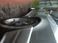
Now that the pipe was out of the engine bay, getting it forward of the splash shield was pretty easy. I was concerned about the tire throwing rocks into the silicone coupler and thin walled flexible stainless intake pipe. So I made a shield for it. I think once the paint fades and it gets dirty it will be almost unnoticeable. There is no chance of the tire contacting it.
- Attachments
-
- IntakeCutoutMOD.jpg (93.09 KiB) Viewed 10033 times
-
Greg Gordon
- Verde
- Posts: 1552
- Joined: Mon Nov 29, 2004 7:06 pm
Next I ran the pipe to the filer. This was a no brainer. I located the filter up really high to avoid any chance of hydro lock. As long as the front bumper is above water, so is the filter. I also flared the filter's inlet so it can't slip off the silicone coupler. The filter can be cleaned and removed by removing the forward splash shield.
- Attachments
-
- Intake2MOD.jpg (100.16 KiB) Viewed 10031 times
-
Greg Gordon
- Verde
- Posts: 1552
- Joined: Mon Nov 29, 2004 7:06 pm
The heat exchanger was visible in that last picture, so I might as well show it next. The heat exchanger is a modern design that's supposed to be really efficient. It has deep fins that are supposed to reduce the need for ducting. The idea is that when air hits it, the air goes through not around it. I will let you guys know how that works out. It's still too early to tell. UPDATE, it needs ducting, no question about that, I will detail the issue on page three of this thread.
The intercooler pump is located forward of the right side front splash shield. You can see it and all the associated hoses in this picture. This exact location proved unsatisfactory and I relocated the pump a few inches lower. As you can see the intercoolers hoses are routed into the engine bay via the factory's fresh air duct.
The intercooler pump is located forward of the right side front splash shield. You can see it and all the associated hoses in this picture. This exact location proved unsatisfactory and I relocated the pump a few inches lower. As you can see the intercoolers hoses are routed into the engine bay via the factory's fresh air duct.
- Attachments
-
- HeatExchangerMOD.jpg (136.28 KiB) Viewed 10028 times
Last edited by Greg Gordon on Tue Feb 26, 2008 7:02 pm, edited 1 time in total.

-
Greg Gordon
- Verde
- Posts: 1552
- Joined: Mon Nov 29, 2004 7:06 pm
Next is the engine bay. A few items are censored for now.
This customer really likes BLACK. Yellow couplers just don't do it for him. It's a big sea of black in there, and it's about to get blacker. All the stainless steel parts are going to be powder coated......black. It sure makes it harder to work on when every vacuum, fuel, coolant, A/C, and intercooler hose are all black. However, it gives it a more "oem" look, and that's what he wants. I must admit, I like it. It has sort of a sinister look to it. The coupler at the supercharger's outlet is actually Yellow covered in Mylar. I couldn't get a black 3.00"-2.75" coupler so that was my only good option.
The intercooler outlet design has been improved since the SuperRedVerde project. Barry suggested it should be more cone shaped. The old one actually was sort of cone shaped internally, but this one is better.
Sharp observers will notice the SDS air intake sensor and water injection nozzle are located on this pipe. There is another air intake temp sensor located in the plenum for the Nordskog gauge.
This engine compartment has A/C and cruise control. I am very pleased that in spite of that, access to the spark plugs and oil filter is at least as good as on a stock GTV6. NOTHING needs to be removed to get at the plugs or oil filter. I have put a lot of thought into service issues. It also has a custom longer dipstick and dipstick holder to make it easy to check the oil.
- Attachments
-
- LesEngineDoneMOD1.jpg (217.44 KiB) Viewed 10019 times
Last edited by Greg Gordon on Fri Feb 15, 2008 8:55 pm, edited 2 times in total.

-
Greg Gordon
- Verde
- Posts: 1552
- Joined: Mon Nov 29, 2004 7:06 pm
Thanks Garth,
The car is super quick. It won't make it to the dyno shop for another couple weeks. I have high hopes that it will put down some good numbers.
The motor has my new 8.5:1 forged NON interference pistons. They are a radical design, very different from my 8.8:1 3 liter pistons, and I admit I was a little nervous about them. If they didn't work, I would have to change them at my expense. It turns out they perform really well. It has very low octane fuel in it, and no signs of knock. It also has a lot of power. Once these pistons have proven they have good long term durability I will put them on my site.
Other than the pistons the motor is a stock GTV6 2.5 with 164 cams. I don't know if they are "S" cams or regular 164 cams. I can't figure that out. They measured 9.4mm of intake lift.
The car has my other usual mods. Cross bolted transaxle mounts (no vibrations), Performatek's clutch, a SZ spherical bearing (that doesn't creak), and SZ vented rotors. So, it's equipped to handle the power. It also has a 4.10 gearbox with a lightened gear set.
Last edited by Greg Gordon on Fri Feb 15, 2008 8:40 pm, edited 1 time in total.
-
Greg Gordon
- Verde
- Posts: 1552
- Joined: Mon Nov 29, 2004 7:06 pm
deleted, accidental double post
Last edited by Greg Gordon on Fri Feb 15, 2008 8:58 pm, edited 1 time in total.
-
Greg Gordon
- Verde
- Posts: 1552
- Joined: Mon Nov 29, 2004 7:06 pm
The next picture shows the supercharger's intake pretty well. It also shows the pipe connecting the supercharger to the intercooler. The supercharger's outlet is 3 inches, and it has to be in order to unshroud the rotors. The intercooler's inlet is 2 inches. The silicone coupler on the supercharger transitions the size down to 2.75" and from there a cone takes it down to 2".
The intercooler is a G.M.C. Syclone unit, and I consider that to be an excellent intercooler. The intercooler pump is a Bosch pump made for the 03'/04' supercharged Cobras.
The intercooler is a G.M.C. Syclone unit, and I consider that to be an excellent intercooler. The intercooler pump is a Bosch pump made for the 03'/04' supercharged Cobras.
- Attachments
-
- LesEngineDoneMOD2.jpg (191.28 KiB) Viewed 10010 times
-
Greg Gordon
- Verde
- Posts: 1552
- Joined: Mon Nov 29, 2004 7:06 pm
That's all for tonight. I will post more pictures in a day or two. Perhaps a video would be fun.
Greg Gordon,
www.hiperformancestore.com
Greg Gordon,
www.hiperformancestore.com